Introduction
In the vast and complex landscape of industrial fluid control, few components are as foundational or widely utilized as the linear motion valve. Whether managing the flow of crude oil through thousands of miles of cross-country pipelines, regulating high-pressure steam in a power generation facility, or controlling municipal water distribution systems, industrial processes rely heavily on the ability to start, stop, and direct media safely and efficiently. At the heart of this operational capability sits the gate valve, a classic yet exceptionally robust device designed to regulate fluid flow with minimal resistance.
Understanding how a gate valve operates, its structural anatomy, its inherent advantages, and its operational limitations is crucial for engineers, plant operators, maintenance personnel, and anyone involved in system design. While modern fluid control technology features a diverse array of rotary and linear options-such as ball valves, butterfly valves, and globe valves-the gate valve remains the undisputed workhorse for isolation services. This comprehensive guide explores the fundamentals of gate valves, breaking down their design principles, mechanical variations, operational characteristics, and industrial applications to provide a thorough understanding of why they remain indispensable in modern engineering.
What is a Gate Valve?
The Linear Motion Principle
To understand a gate valve, one must first comprehend the broader category to which it belongs: linear motion valves. Unlike rotary valves, which control flow by rotating an internal element (such as a ball or a disc) perpendicular to or within the flow stream, linear motion valves operate by moving the closure member along a straight line. The closure member-in this case, the "gate"-moves up and down perpendicular to the path of the fluid.
When the gate valve is fully opened, the gate is completely withdrawn from the flow path, leaving an opening roughly the same internal diameter as the pipe itself. This design characteristic is one of the defining features of the gate valve, distinguishing it from globe or butterfly valves that inherently obstruct the flow path even when fully open. Because the flow path remains unobstructed, the media experiences very little turbulence and pressure drop as it passes through the valve.
Key Internal Components
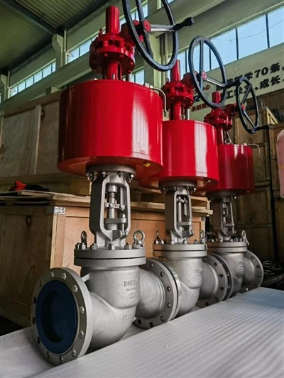
A standard gate valve is constructed from several precision-engineered components that work in unison to ensure reliable isolation.
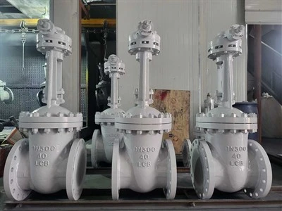
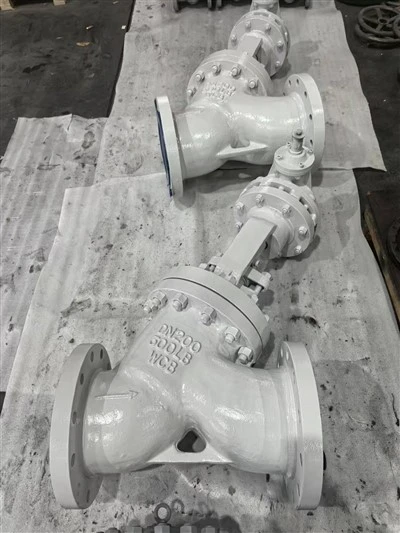
The Body: The main pressure-containing enclosure that connects to the piping system through flanges, threaded joints, or welded ends. It houses the internal flow path and seating surfaces.
The Bonnet: Attached to the body, the bonnet provides a secure, leak-proof closure for the valve body. It houses the stem and allows access to the internal components for maintenance. Bonnets can be screwed, bolted, or pressure-sealed depending on the pressure rating of the valve.
The Gate (or Disc): The barrier element that slides up and down to open or close the valve. Gates are manufactured in various geometric shapes to suit different application requirements, including solid wedges, flexible wedges, and split discs.
The Seats: The surfaces against which the gate presses to form a tight seal when the valve is closed. Gate valves typically feature two seats-one on the upstream side and one on the downstream side.
The Stem: The threaded rod that connects the actuator or handwheel to the gate, transmitting the mechanical force required to raise or lower the closure member.
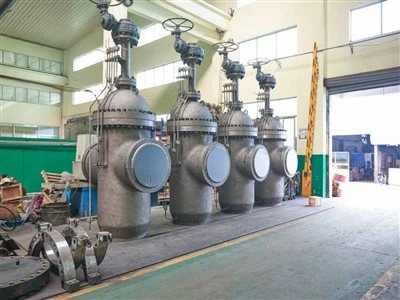
The Actuator: The mechanism used to operate the stem, which can be a manual handwheel, gear operator, pneumatic actuator, electric motor, or hydraulic cylinder.
The Packing: A fibrous or molded sealing material housed in the stuffing box that prevents process media from leaking out of the valve around the stem.
Working Mechanism and Operation
Open Versus Closed States
The operational lifecycle of a gate valve is defined primarily by its two extreme positions: fully open and fully closed. When a gate valve is in the open position, the gate is retracted entirely into the valve bonnet. The fluid flows straight through the valve body with maximum cross-sectional area, resulting in an exceptionally low pressure drop across the valve. This makes gate valves ideal for applications where maintaining fluid momentum and minimizing energy loss are paramount.
Conversely, rotating the handwheel in the closing direction drives the stem downward, pushing the gate into the flow path until it firmly seats against both the upstream and downstream seating surfaces. The wedging action forces the gate tightly against the seats, creating a metal-to-metal (or resilient-seated) barrier that halts fluid migration.
Rising Versus Non-Rising Stems
Gate valves are fundamentally categorized by how their stems move during operation, a design distinction that impacts spatial requirements and operational safety.
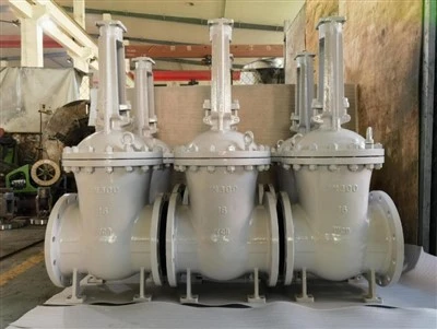
A rising stem gate valve features a stem that is rigidly attached to the gate. As the handwheel is turned, the stem moves upward along with the gate. This design provides a clear visual indicator of the valve's position-if the stem is extended above the handwheel, the valve is open; if it is flush or lowered, the valve is closed. However, rising stem valves require additional vertical clearance above the actuator to accommodate the rising stem during operation. They are typically used in above-ground installations where visual position indication is advantageous.
A non-rising stem gate valve features a stem that is threaded into the gate itself. As the handwheel is rotated, the stem rotates in place, causing the gate to travel up or down the threaded shaft without the stem itself moving vertically. Because the overall height of the valve remains constant regardless of its open or closed state, non-rising stem gate valves are ideal for space-restricted environments, underground installations, or maritime applications where vertical clearance is at a strict premium.
Advantages and Limitations of Gate Valves
Key Benefits
The enduring popularity of the gate valve across heavy industries stems from a distinct set of operational advantages that other valve types cannot easily replicate.
Minimal Pressure Drop: Because the internal bore of an open gate valve matches the inner diameter of the connected pipe, fluid flows through with virtually zero obstruction. This eliminates turbulence and pressure loss, reducing pumping energy costs over long pipeline networks.
Bi-Directional Flow Capability: Most gate valves are symmetric in their internal design, allowing fluid to pass through in either direction without compromising sealing integrity or performance. This simplifies piping design and eliminates installation errors related to flow orientation.
Reliable Shut-Off: When fully closed, a gate valve provides a remarkably tight seal against high-pressure media, making it an exceptional isolation valve for critical shutdown and maintenance procedures.
Simplicity and Versatility: The mechanical design is straightforward, meaning fewer potential failure points. They can handle a vast range of temperatures, pressures, and corrosive media when manufactured from appropriate metallurgical alloys.
Operational Limitations
Despite their numerous strengths, gate valves are specialized tools and possess distinct limitations that dictate when and where they should be deployed.
Unsuitability for Throttling: Gate valves must never be used to regulate or throttle flow rates. When a gate valve is partially opened, the high-velocity fluid rushing through the narrow opening causes intense vibration, turbulence, and mechanical chatter against the partially exposed gate. This phenomenon, known as wire-drawing, rapidly erodes the seating surfaces, deforms the gate, and leads to premature valve failure and leakage. Gate valves are strictly designed for on-off, isolation-only service.
Slow Actuation Speeds: Because opening or closing a gate valve requires multiple complete rotations of the handwheel or stem, actuation is inherently slow. While this characteristic prevents dangerous water hammer effects by ensuring gradual closure, it renders gate valves impractical for emergency shutdown scenarios that demand rapid response times.
High Operating Torque: In high-pressure applications, the friction between the gate and the seats under heavy fluid loads can generate significant operational torque, often necessitating the incorporation of gearboxes or automated actuators to open and close the valve safely.
Common Types and Configurations
Solid, Flexible, and Split Wedge Designs
To address varying thermal expansion rates, mechanical stresses, and sealing challenges, manufacturers produce gate valves with different gate configurations.
The solid wedge is the most common and robust gate design. It consists of a single piece of solid metal shaped like a wedge. Its simplicity makes it exceptionally durable and suitable for a wide variety of liquid and gas applications. However, solid wedge gate valves are susceptible to thermal binding; if a pipeline cools rapidly after being exposed to high temperatures, the valve body can contract around the solid wedge, making it exceedingly difficult to reopen without specialized thermal management or mechanical force.
To combat the issue of thermal binding, engineers developed the flexible wedge gate valve. A flexible wedge features a peripheral cut or groove around the perimeter of the solid metal disc, allowing the seating faces to flex slightly. This compliance enables the gate to adjust its angle to match minor misalignments or distortions in the valve body caused by pipe stress or thermal cycling, ensuring a tight seal without jamming.
The split wedge (or parallel disc) gate valve consists of two separate circular discs held together by a special mechanism that allows them to adjust independently against the upstream and downstream seats. This design is exceptionally effective for handling corrosive gases or high-temperature steam lines where thermal distortion of the valve body is a frequent concern.
Parallel Slide Gate Valves
Unlike wedge-style gate valves that rely on a wedging action to create mechanical sealing pressure, parallel slide gate valves utilize two parallel discs pressed against parallel seats by line pressure or an internal spring mechanism. This design is particularly favored in high-pressure steam power plants and high-temperature industrial pipelines because it prevents the mechanical locking common in wedge designs under extreme thermal expansion cycles.
Industry Applications and Selection Criteria
Where Are They Used?
The versatility, durability, and reliable shut-off performance of the gate valve make it a cornerstone component across numerous industrial sectors:
Oil and Gas Upstream and Midstream: Used extensively in wellheads, gathering systems, refining facilities, and long-distance transmission pipelines to isolate sections of piping for pigging operations or emergency repairs.
Power Generation: Utilized in fossil fuel and nuclear power plants to manage high-pressure boiler feed water, condenser systems, and steam distribution lines.
Water and Wastewater Treatment: Employed in large-scale municipal water mains, distribution networks, and treatment plants where full-bore flow and reliable isolation of large pipe diameters are critical.
Chemical and Petrochemical Processing: Installed in chemical plants to handle aggressive fluids, hydrocarbons, and corrosive slurries, utilizing specialized alloys such as stainless steel, Monel, or Hastelloy.
Factors to Consider When Specifying a Valve
When selecting a gate valve for a specific engineering project, several critical technical parameters must be evaluated to ensure safety, longevity, and optimal performance:
Pressure and Temperature Ratings: The valve body, bonnet, and internal trim must be rated to withstand the maximum allowable working pressure (MAWP) and thermal extremes of the operating environment.
Material Compatibility: The metallurgical composition of the valve body and internal components must match or exceed the corrosive and erosive properties of the process fluid. Common materials range from standard carbon steel and ductile iron to exotic stainless steels and nickel alloys.
End Connections: Selection depends on pipe size and installation requirements, including flanged ends for easy removal, socket-weld or butt-weld ends for high-pressure permanent installations, and threaded ends for smaller utility lines.
Size and Actuation Requirements: Proper sizing ensures that the valve matches the pipeline internal diameter, while actuator specification determines whether manual handwheels, gearboxes, or automated electrical/pneumatic drives are required based on operational frequency and accessibility.
Conclusion
The gate valve stands as a timeless testament to effective mechanical design. By fulfilling the fundamental requirement of providing an unobstructed flow path in its open state and a reliable, leak-tight seal in its closed state, it has earned an indispensable place in modern industrial engineering. While it is not designed for flow regulation or rapid actuation, its unmatched capability for bi-directional isolation with minimal pressure drop makes it the premier choice for major pipeline infrastructure, power plants, and processing facilities worldwide.
A thorough understanding of its linear motion mechanics, internal configurations, operational advantages, and inherent limitations empowers engineers and operators to specify the right valve for the job, ensuring system safety, energy efficiency, and long-term operational reliability across diverse industrial landscapes.